I. Basic Knowledge
1. Understand the Timing System
The timing system mainly consists of four components: the timing devices, UHF antennas, bib numbers & Ultra Tag chips, and the Run8 Cloud timing backend.
1.1 Timing devices are mainly divided into the following two types, as shown in Table 1.1.
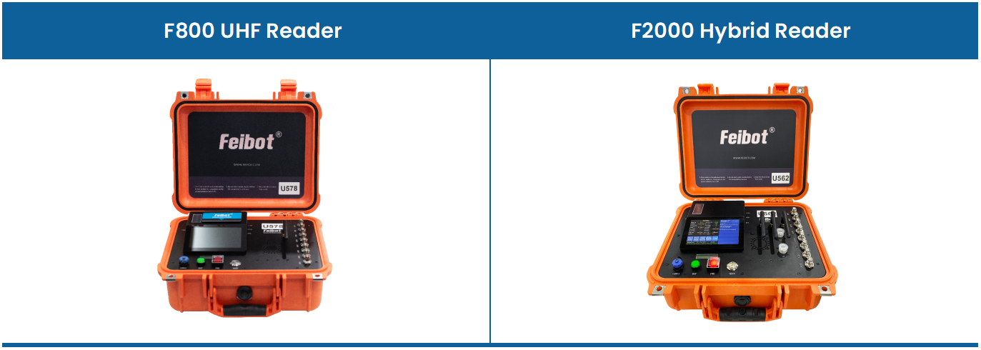
Table 1.1: Product illustrations of different model timing devices
(1) F800 Reader: UHF reader box. Detailed usage guide: wiki: https://wiki.feibot.com/bd2f/5a01/a7d0
(2) F2000 Hybrid Reader: Active and passive hybrid reader box. Detailed usage guide: wiki: https://wiki.feibot.com/bd2f/eb1d/0c28

1.2 UHF Antennas are mainly divided into the following four types, as shown in Table 1.2.
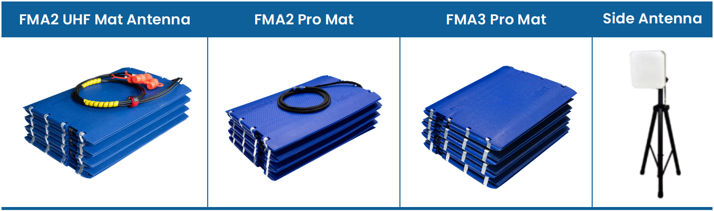
Table 1.2: Product illustrations of different model UHF antennas
(1) FMA2 UHF Mat Antenna: Embedded UHF antenna and low-loss feed line. Detailed usage guide: wiki: https://wiki.feibot.com/bd2f/1cc2/da26
(2) FMA2 Pro Mat: Embedded a reader module. Detailed usage guide: wiki: https://wiki.feibot.com/bd2f/587d/9d54
(3) FMA3 Pro Mat: Embedded a reader module. Detailed usage guide: wiki: https://wiki.feibot.com/bd2f/d335/0c04
(4) Side Antenna: Wide reading range, can be used with both the device and mat simultaneously.

1.3 Bib Numbers and Ultra Tag Chips
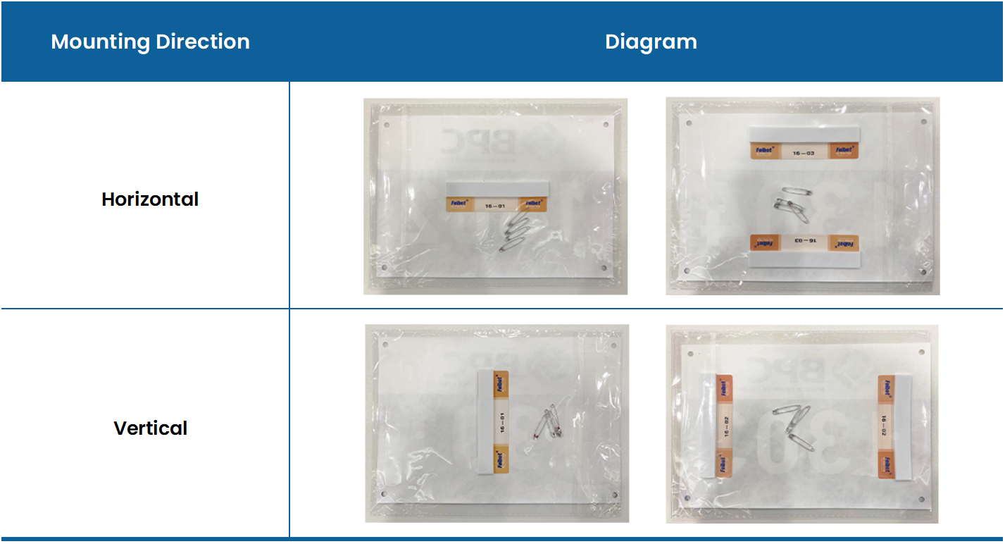
Figure 1.3: Diagram of chip mounting direction

1.4 Run8 Cloud Timing Backend
Main features: event creation, event management, result display, finishing certificates, etc.

2. Understand the Timing System Workflow
First, connect the timing device to the UHF antenna. When the bib, which has a timing chip attached, enters the reading range of the UHF antenna, the timing device reads the data from the timing chip via the UHF antenna. Then, the device uploads the read chip data to the Run8 Cloud timing backend via the network and calculates the corresponding results based on the pre-set timing rules.

II. Quick Start Guide
1. Preparation on the Day Before the Event
1.1 Prepare the Timing Backend
(1) Create the Event
Enter the event management page in the Run8 Cloud timing backend, click the "+ New" button in the top right corner, and enter the "create" page. After filling in the relevant information, click the "Submit" button to complete the creation of the new event (as shown in Figure 2.1.)
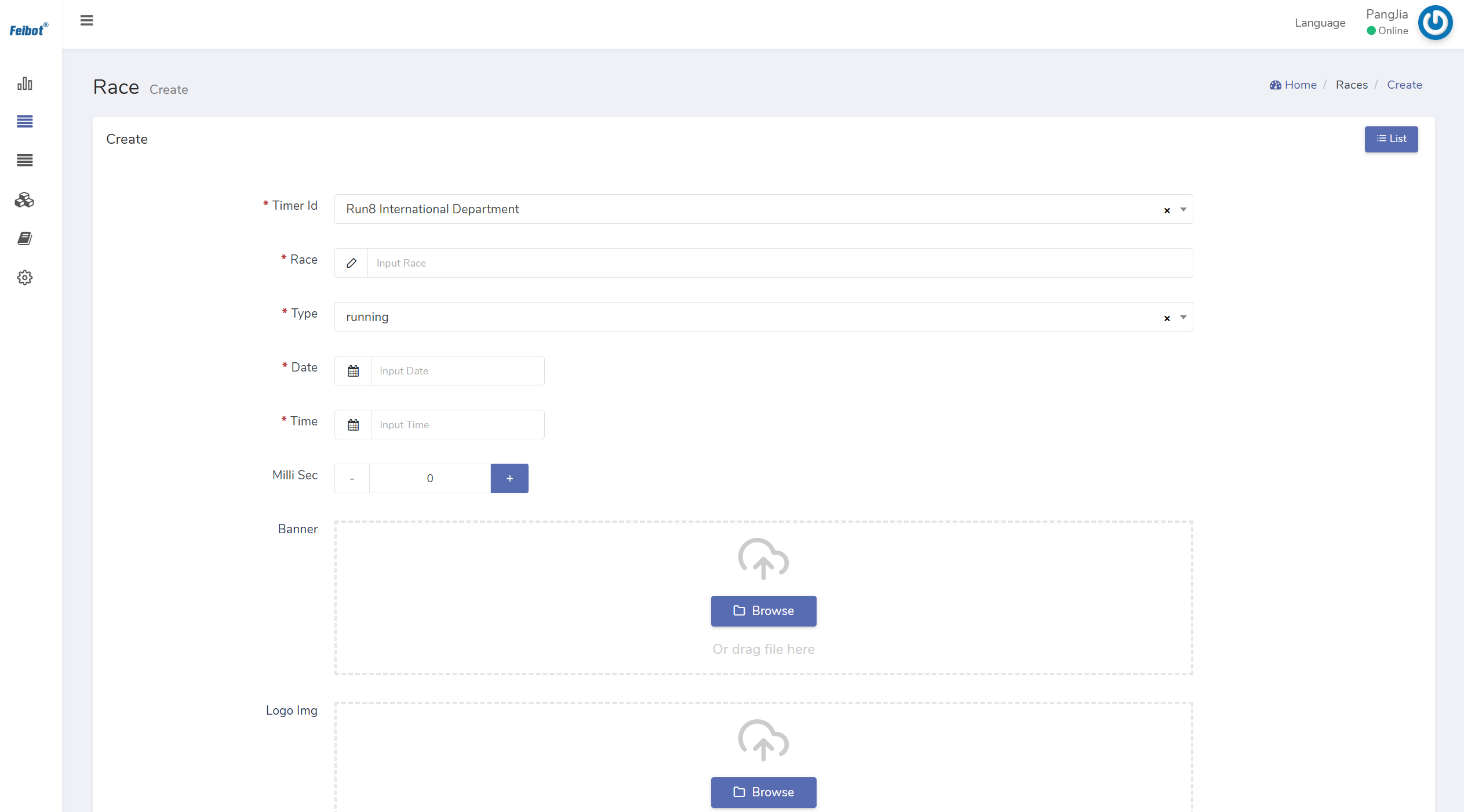
Figure 2.1: Create the event page

(2) Upload the Runner List
Enter the runner list page in the Run8 Cloud timing backend. Click the "Export" button in the top right corner. Based on the exported Excel list template, edit the participant information according to the column headers and save the file. Then, return to the runner list page, click the "import" button in the top left corner, and upload the list to the backend (as shown in Figure 2.2.)
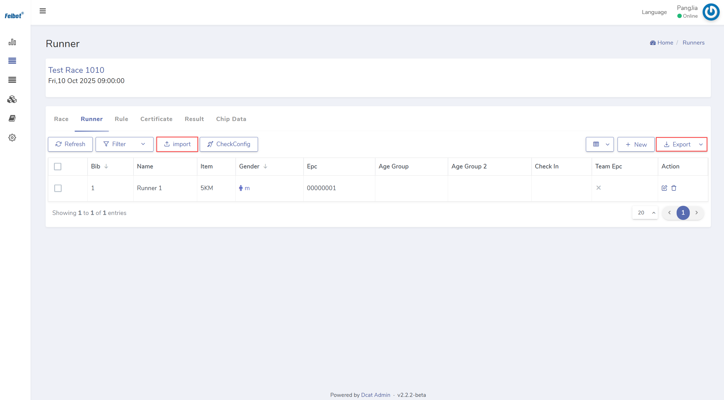
Figure 2.2: Runner list page

(3) Set Timing Rules
Click on the newly created event to enter the "Rule Configs" page for the event. Click the "+ New" button in the top right corner to set the timing rules. Afterward, click the "Submit" button to complete the setup of the event's first timing rule (as shown in Figure 2.3.) Depending on the timing needs of the event, you can continue clicking the "+ New" button to set multiple timing rules for various timing points (as shown in Figure 2.4.)
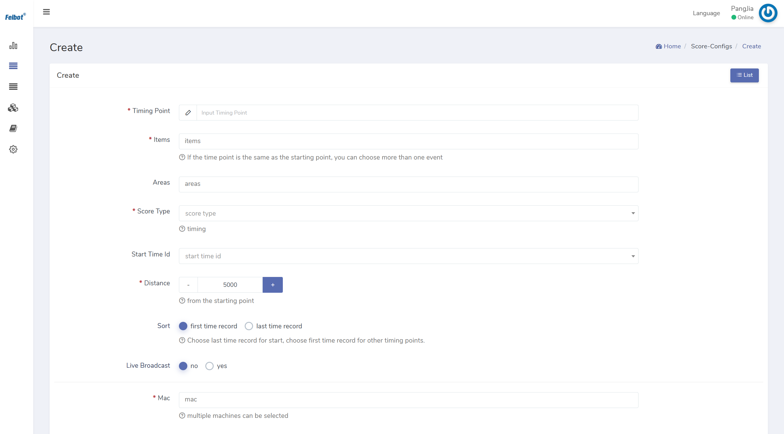
Figure 2.3: Event rules setting page
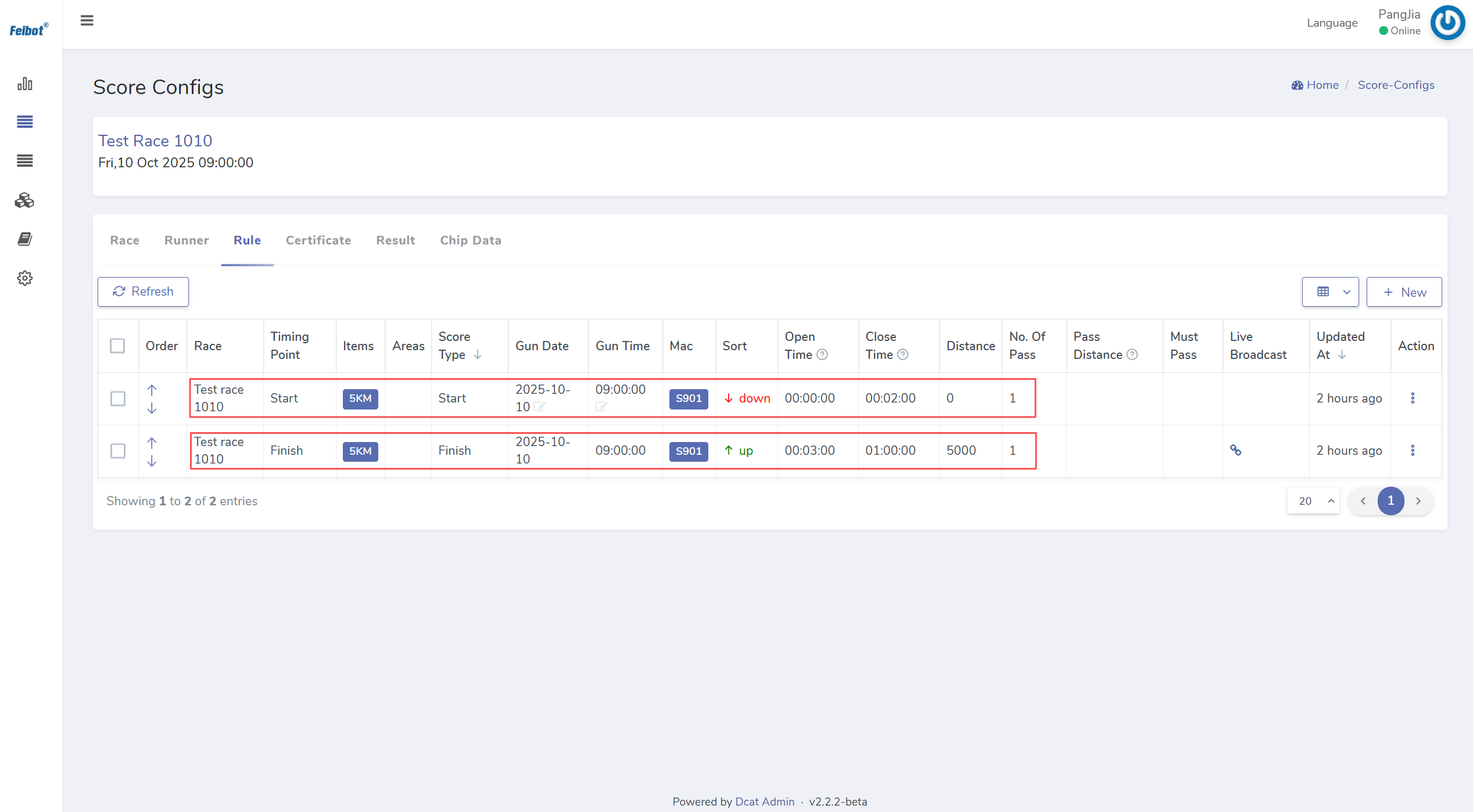
Figure 2.4: Multiple timing point rules setting page

1.2 Prepare the Timing Devices and Check the Mats/Mat Antennas
(1) Charge the Timing Device
Each timing device is equipped with a dedicated lithium battery. For safety reasons, please ensure that staff are present while charging the timing device.

(2) Connect the Timing Device to the Network
Users can choose from the following three networking methods:
- Wired Network Connection: Connect the provided network cable to the Ethernet port of the timing device.
- USB Device Connection: Connect a USB-enabled internet device to the USB port of the timing device.
- WiFi Connection: Tap the WiFi icon on the device screen and select the corresponding wireless network to connect.

(3) Download Config Files
During official events, multiple timing devices are deployed at different timing points. To accurately determine the specific location of each timing device, users need to set up the timing devices and their corresponding locations in the Run8 Cloud timing backend. When the timing device is connected to the network, click "download config file" to transfer the configured timing information to the device. Users can easily view the event and timing point of each timing device through its screen (as shown in Figure 2.5.)
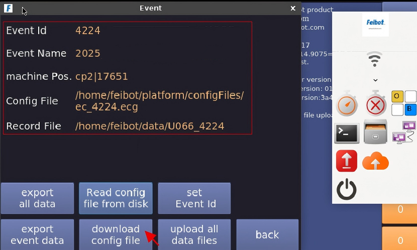
Figure 2.5: Download config file page

(4) Check the Device Time - Time synchronization of the timing device
Before the official event, it is necessary to verify the date and time of the timing device and ensure that the reference time is consistent across multiple timing devices. The specific steps are as follows: Select one timing device, adjust and verify its time to match the local time, then use the wireless time synchronization feature to synchronize this timing device's time with the others, or manually adjust the time to ensure the reference time of all timing devices used in the event is the same (as shown in Figure 2.6.)
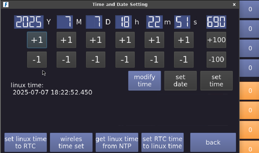
Figure 2.6: Time and date setting page

(5) Check Normal Reading
The check of the timing device's reading feature mainly covers: reader type, working band, and reader power. Each timing device can connect to two readers. When using the system, ensure that the readers connected to the same timing device are set the same (as shown in Figure 2.7.)
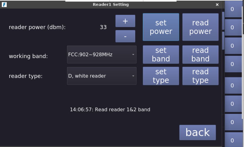
Figure 2.7: Reader setting page

(6) Test Mat Reading Distance
Connect the timing device to the UHF antenna. The user can hold the chip and stand 1.5 meters away from the mat to test whether each mat can properly read the chip. If the chip is successfully read, the timing device's beeper will sound, and the corresponding number of chips read by the mat will be displayed at the reader button on the right side of the screen (as shown in Figure 2.8.) If a mat cannot read the chip or requires a closer distance to read it, it indicates that the mat's antenna may be damaged and needs to be replaced or repaired.
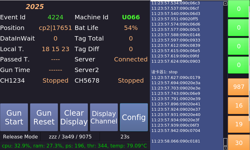
Figure 2.8: The timing device chip reading page

(7) Check the Normal Upload of Data
The user can modify the event time in the Run8 Cloud timing backend to the current time, then use the timing device connected to the UHF antenna to read the chip data, simulating the upload of event data in advance. In the "Chip Data" page of the Run8 Cloud timing backend, the user can view all the chip data read and uploaded to the backend by the timing device (as shown in Figure 2.9.)
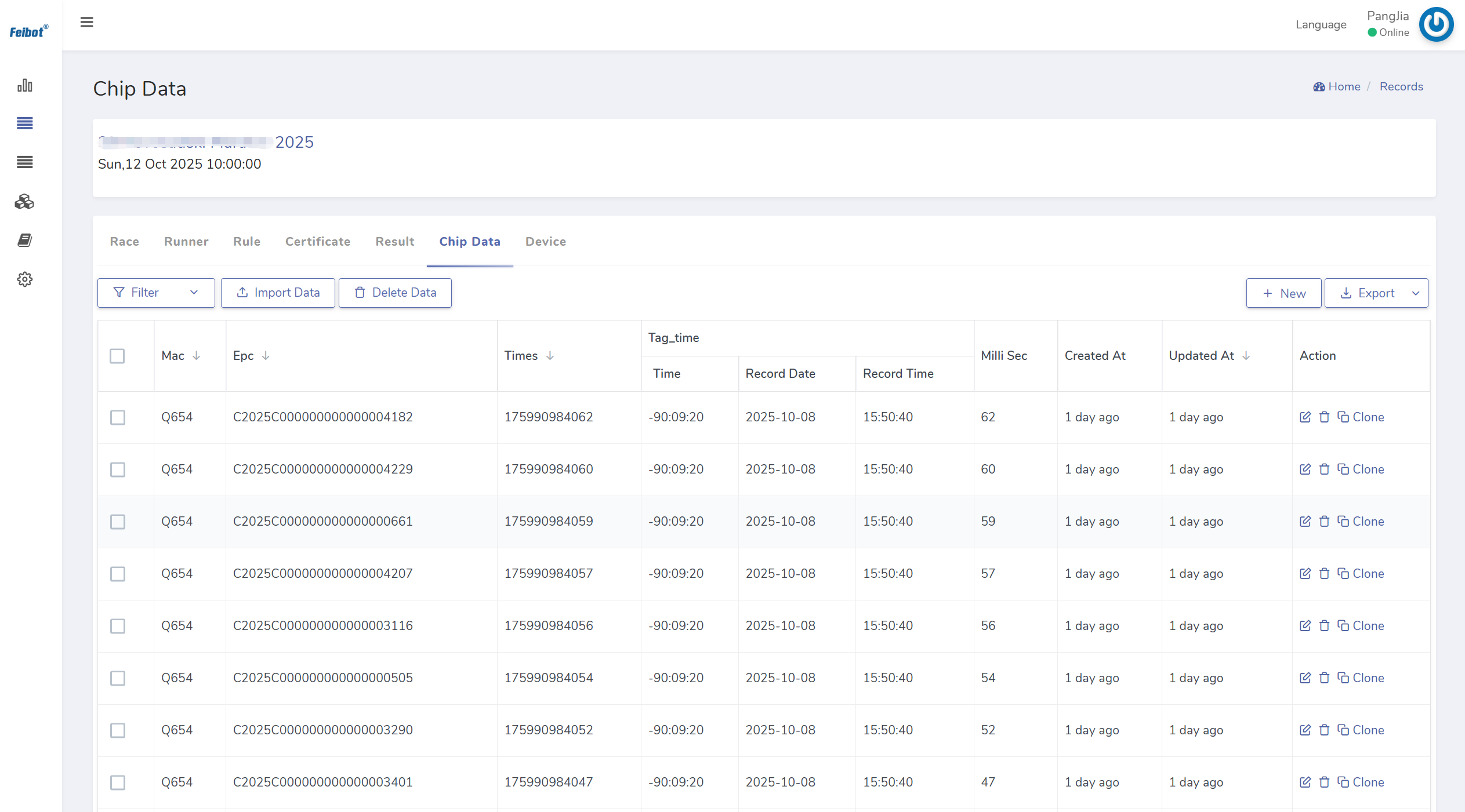
Figure 2.9: Chip data page

1.3 Prepare the Timing Chip
(1) Pay Attention to the Attachment Direction
The mat antenna has two polarization directions: horizontal and vertical. For a horizontal antenna, the timing chip must be attached horizontally in order to be read; for a vertical antenna, the timing chip must be attached vertically to be read. Therefore, before using the chip, ensure that you confirm the polarization direction of the mat antenna being used, and make sure the attachment direction of the chip aligns with the antenna's polarization direction.

(2) Distribute Timing Chips to Participants
Verify the participant's identity information. Once confirmed, distribute the corresponding timing chip and bib number to the participant. The distribution information must match the details in the runner list.

2. Preparation 2 Hours Before the Event
2.1 Lay the Mat Antenna/Mat
To better use the timing devices and the induction antennas, we provide the following layout options based on different timing devices and UHF antenna models.
(1) FMA2 UHF Mat Antenna
A. A single FMA2 UHF Mat Antenna Installation
The FMA2 UHF mat antenna, when in operation, will create an electromagnetic induction area within a 2-meter range in front and behind it. The induction area is shown in Figure 2.10.
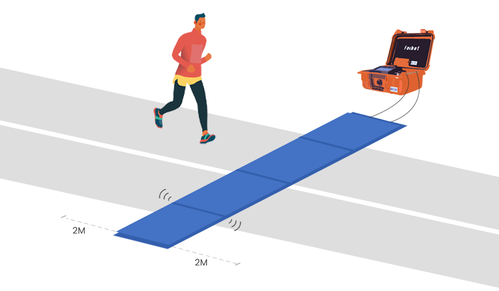
Figure 2.10: Schematic diagram of a single FMA2 UHF mat antenna installation

B. Multiple Sets of FMA2 UHF Mat Antennas Installation
When using multiple sets of FMA2 UHF mat antennas, the following should be noted: The distance between any two mat antennas should be maintained between 5 to 6 meters. When using multiple 8-meter-long FMA2 UHF mat antennas, we typically arrange the devices crosswise, as shown in Figure 2.11.
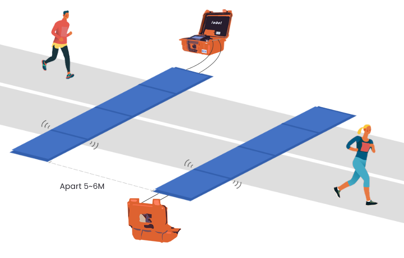
Figure 2.11: Schematic diagram of multiple sets of FMA2 UHF mat antennas installation

C. Combination of FMA2 UHF Mat Antenna with Side Antenna
When the side antenna is in operation, it creates an electromagnetic induction area with a transverse radiation angle of about 70° within a 9-meter range in front of the antenna. When used in conjunction with the FMA2 mat antenna, the first reader of the mat antenna can be disconnected from the reader box, and the side antenna should be connected to that position. Additionally, ensure that a 4-meter distance is maintained between the side antenna and the FMA2 UHF mat antenna, as shown in Figure 2.12.
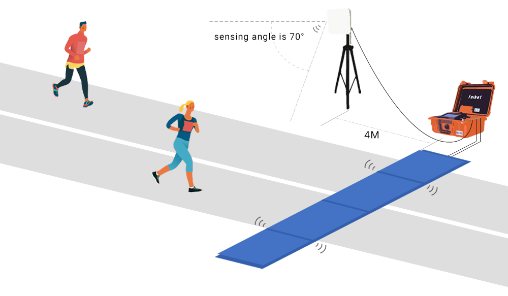
Figure 2.12: Schematic diagram of FMA2 mat antenna used with side antenna

(2) FMA2 Pro Mat
The FMA2 Pro mat is typically used in conbination with the F2000 hybrid reader box.
A. A single FMA2 Pro Mat Installation
When the FMA2 Pro mat is in operation, it creates an electromagnetic induction zone within a range of 3 to 3.5 meters in front of and behind the mat. The induction area is shown in Figure 2.13.
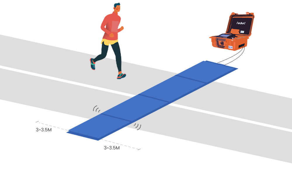
Figure 2.13: Schematic diagram of a single FMA2 Pro mat installation

B. Multiple Sets of FMA2 Pro Mats Installation
When using multiple sets of FMA2 Pro mats together, it is important to note that the distance between any two mats should be maintained at 6 meters. Since the FMA2 Pro mat has a embedded reader and is not affected by feeder cable length, there is no need to lay the mats of multiple connected devices in a crisscross pattern (as shown in Figure 2.14.)
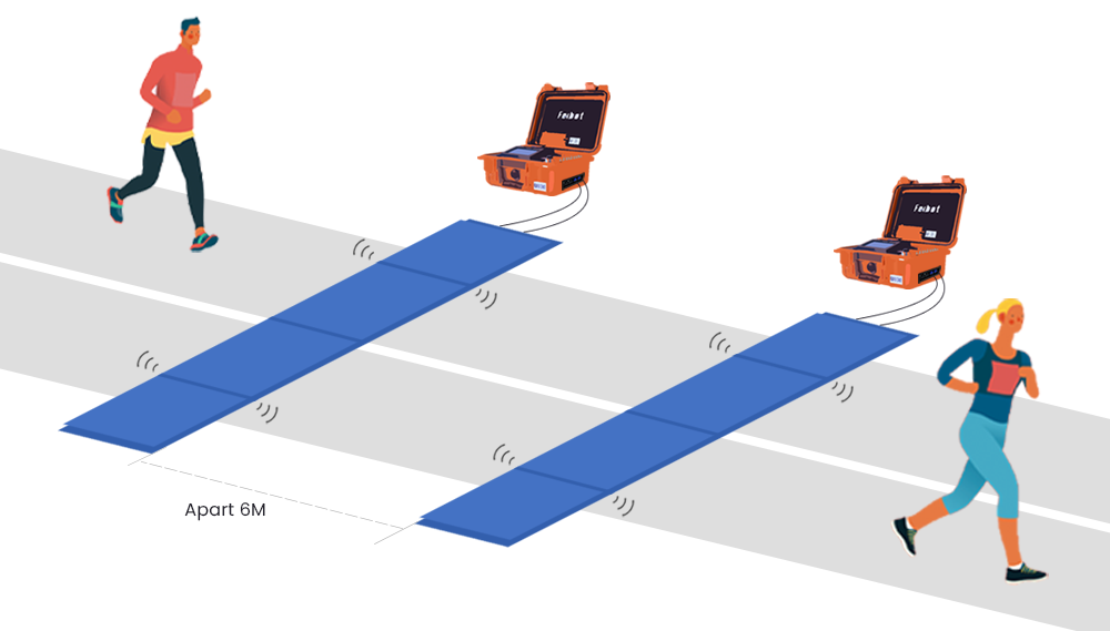
Figure 2.14: Schematic diagram of multiple sets of FMA2 Pro mats installation

C. Combination of FMA2 Pro Mat with Side Antenna
When the side antenna is in use, it creates an electromagnetic induction zone with a transverse radiation angle of about 70° within a 9-meter range in front of the antenna. When used in combination with the FMA2 Pro mat, the side antenna can be connected to the embedded reader of the F2000 hybrid reader, or a separate device can be prepared to connect to the side antenna. Additionally, please ensure that a 4-meter distance is maintained between the side antenna and the FMA2 Pro mat, and the side antenna should not be pointed directly at the mat (as shown in Figure 2.15.)
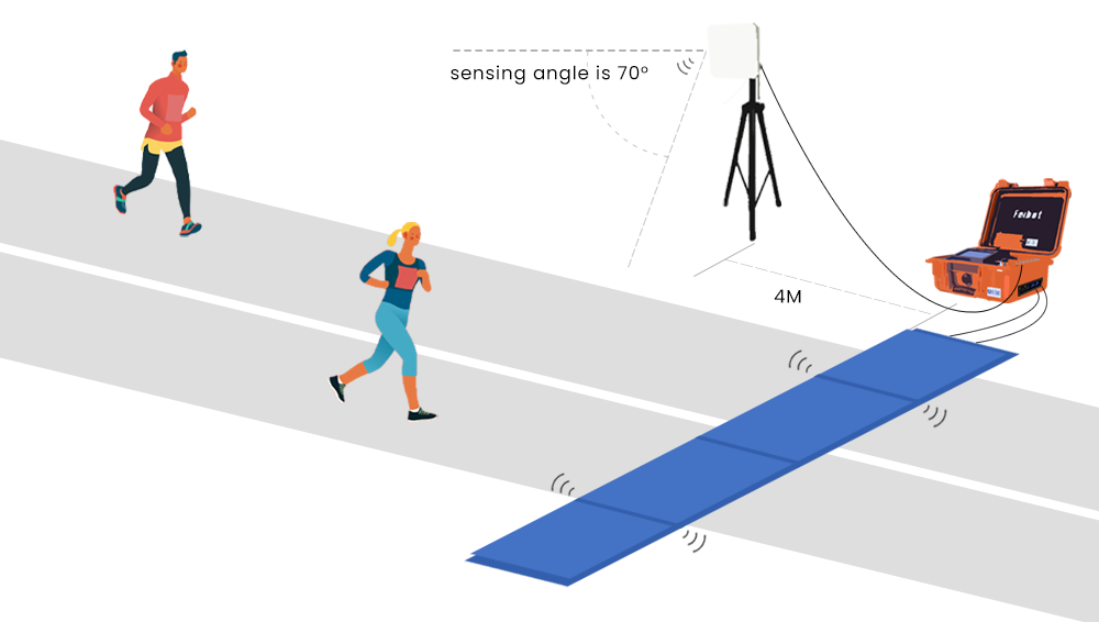
Figure 2.15: Schematic diagram of FMA2 Pro mat used with side antenna

(3) FMA3 Pro Mat
The FMA3 Pro mat is laid in the same way as the FMA2 Pro mat and is typically used in combination with the F2000 hybrid reader box.

(4) Side Antenna
When operating, the side antenna generates an electromagnetic induction zone with a transverse radiation angle of approximately 70° within a 9-meter range in front of it. Below are three application methods for the side antenna:
A. A single side antenna used independently, as shown in Figure 2.16.
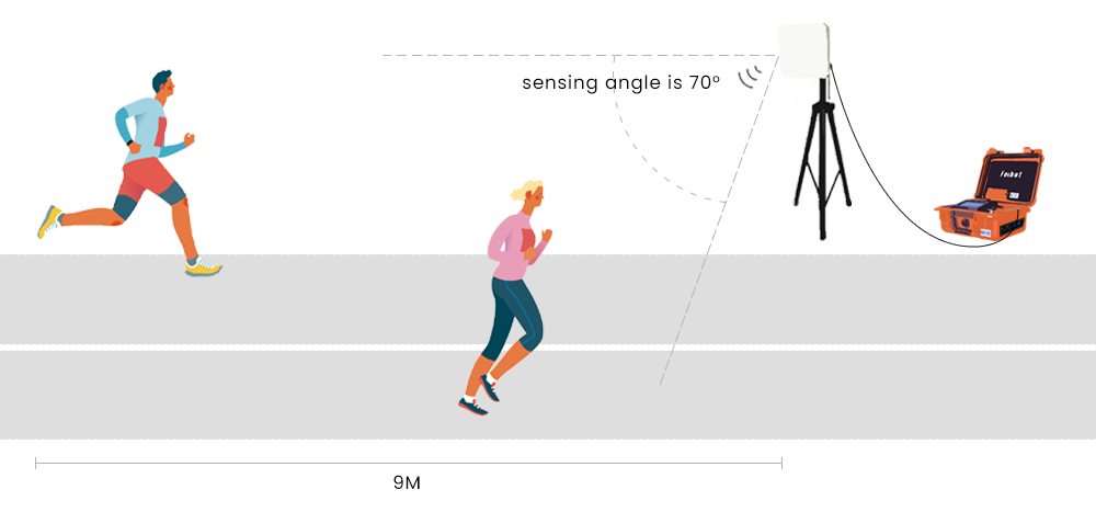
Figure 2.16: Schematic diagram of a single side antenna used independently

B. Multiple Side Antennas Used Together
Due to the wide electromagnetic induction range of the side antenna, when using multiple units, special attention should be paid to their placement and the distance between them, as shown in Figure 2.17.
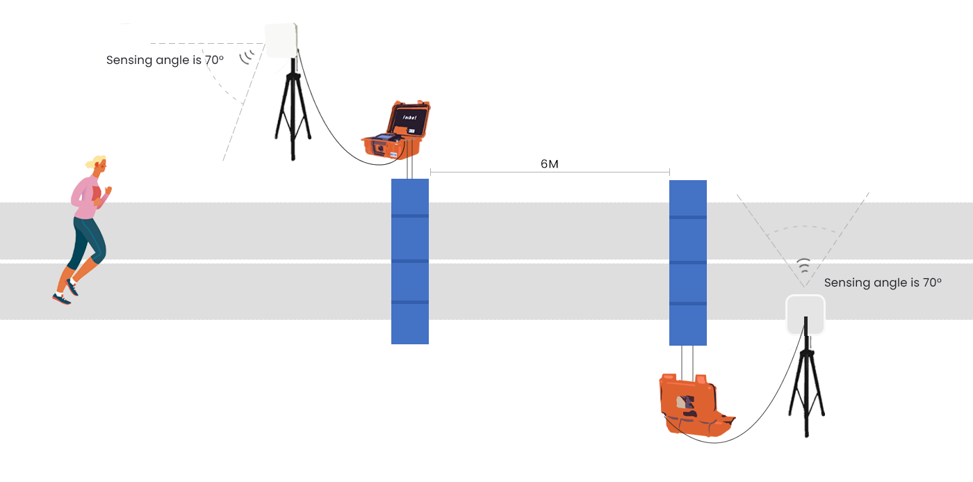
Figure 2.17: Schematic diagram of multiple side antennas used together

C. Side antenna used with mat antenna/mat (refer to the above.)

2.2 Test the Chip Reading
When using the timing device, please ensure that the EPC byte length for the chip to be read is selected. If the byte length is not selected, the corresponding chip will not be detected or read by the timing device (as shown in Figure 2.18.)
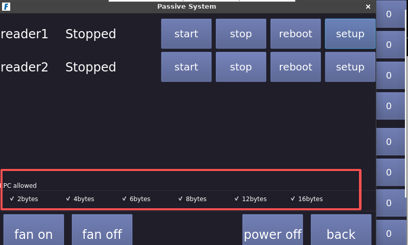
Figure 2.18: EPC byte length setting page

2.3 Check the settings and state of the timing device
(1) Connect the timing device to the network
According to the requirements of the event, you can choose from the following three connection methods:
- Ethernet connection: Connect the provided network cable to the timing device’s network port.
- USB device connection: Connect the internet-enabled USB device to the USB port of the timing device.
- WiFi connection: Click the WiFi icon on the device interface and select the corresponding wireless network to connect.

(2) Select Server
The timing device is pre-configured with the corresponding server at the factory. Please do not change the device's server settings without proper authorization.

(3) Check the Time of the Device
About two hours before the event, recheck if the time on the timing device matches the local time. If the time on a particular device does not match the local time, you can either obtain the network time or manually adjust the time to ensure that all timing devices used in this event have the same reference time (as shown in Figure 2.19.)

Figure 2.19: Time and date setting page

(4) Set Reader Power
Before the official event, set the corresponding reader power to 33 dbm (as shown in Figure 2.20.)
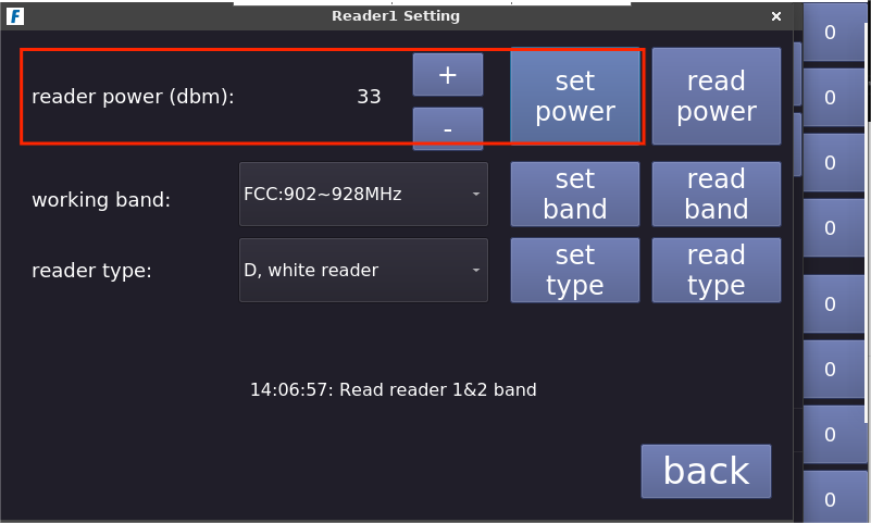
Figure 2.20: Reader power setting page

(5) Check Reader Type and Working Band
The timing device is pre-configured with the reader type and working band before shipment. Do not change the reader type or working band parameters arbitrarily (as shown in Figure 2.21.)
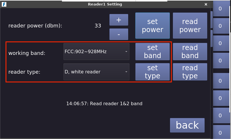
Figure 2.21: Reader type and working band setting page

(6) Check Reader Switch
Each F800 UHF reader box can connect to up to two readers, with each reader able to connect to four antennas. By clicking the corresponding channel button on the device screen, you can independently turn each antenna on/off (the reading channels are displayed on the right side of the screen; the four channels at the bottom correspond to Reader 1, and the four channels at the top correspond to Reader 2.) Note: Each reader can turn off a maximum of three antennas, and this feature can only be used when the reading is stopped (as shown in Figure 2.22.)
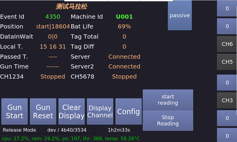
Figure 2.22: Reader switch setting page

3. During the Event
3.1 Monitor Device Operation
Users can filter and view the connection and reading state of the timing device on the "Device State" page in the Run8 Cloud timing backend. If there is a network disconnection or a failure to read, users should promptly contact the onsite staff for inspection and restore the device's network and reading state (as shown in Figure 2.23.)
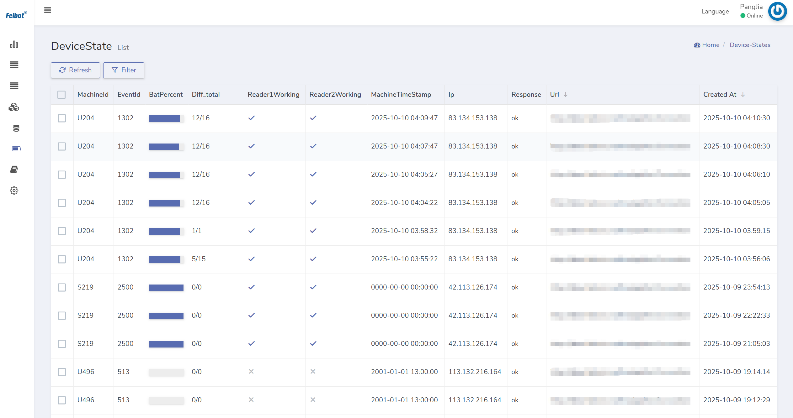
Figure 2.23: Device state page

3.2 Monitor Backend Data
Users can view all chip data read and uploaded by timing devices to the backend in real-time on the "Chip Data" page of the Run8 Cloud timing backend. Users can also filter and view the reading state of a specific chip according to their needs, or check all chip data read by a particular device (as shown in Figure 2.24.)
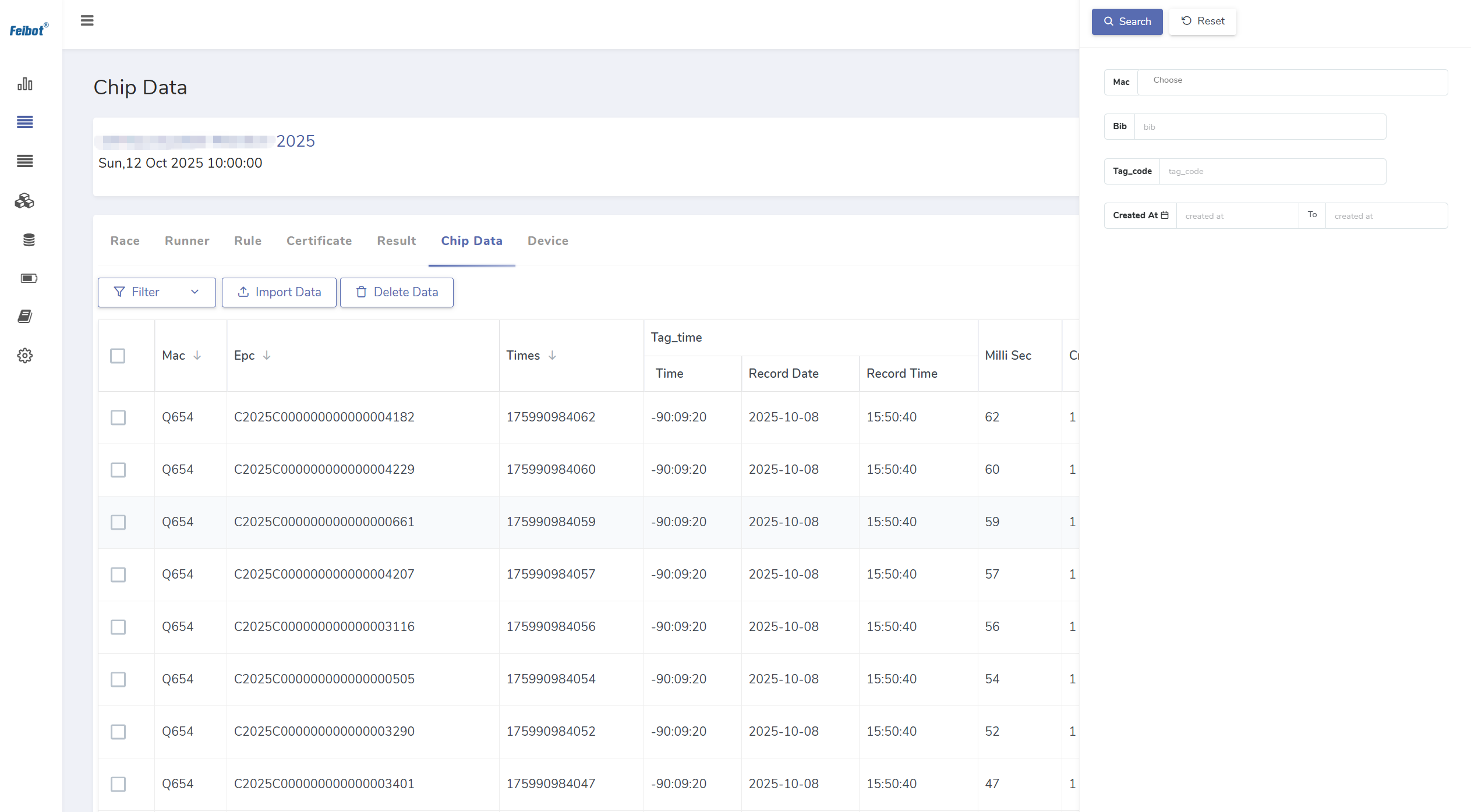
Figure 2.24: Chip data reading state viewing page

3.3 Ensure the Order of the Event
During the event, users can monitor the progress of participants in the timing area and guide them to pass through the timing mats properly. If a participant stands on the mat or obstructs the side antenna, they should be promptly directed to pass through and leave the timing area to avoid affecting the timing of other participants.

4. After the Event
4.1 Check and Export Results
During or after the event, users can calculate the results at various timing points by clicking the "calculate" button on the "Result" page. By clicking the "verify/lock" button, users can verify whether the participants have completed the event normally based on the preset timing rules and distances. Then, users can export the result sheet by clicking the "Export" button (as shown in Figure 2.25.)
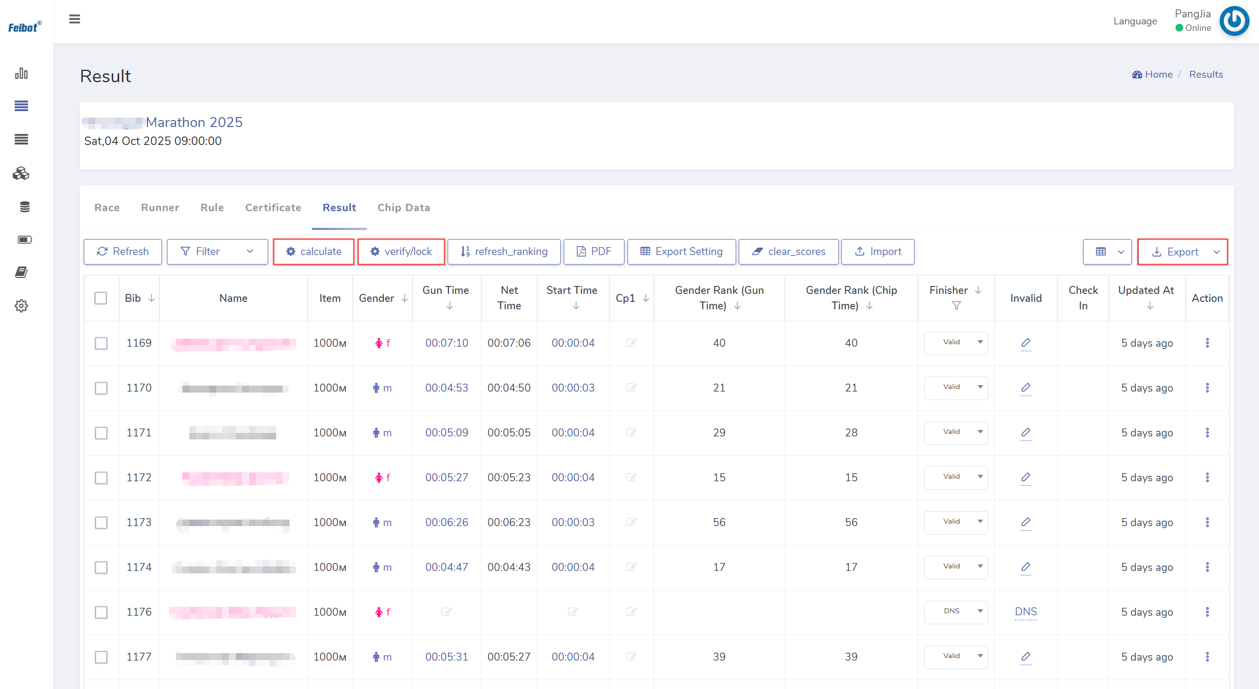
Figure 2.25: Result management page

4.2 Recover Device
After all the timing points are completed, users need to check whether all the data from each timing point has been uploaded. Once the "Pending Data" displayed on the device page shows zero, users should proceed with the inventory and recovery of the timing devices at each timing point (as shown in Figure 2.26.) If it rains during the event, the device should be dried off before being stored after the event concludes.
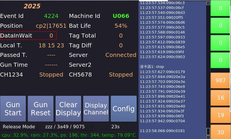
Figure 2.26: Check pending data for device
