I. Device Connection
1. Active System
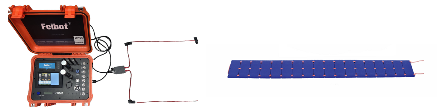
When using the active system feature, LF loop cables and HF antennas need to be connected. The connection method is shown in the diagram below. The LF loop cables are laid out on the track where athletes pass through, with two common installation methods:
- (1) Adhesively attach the cable to the track using a ground mat glue at the top arc. When in use, the wire frame should be kept straight, as any bending may affect timing accuracy.
- (2) The loop cable is embedded inside a dedicated ground mat, which is then laid out on the track.
2. Passive System
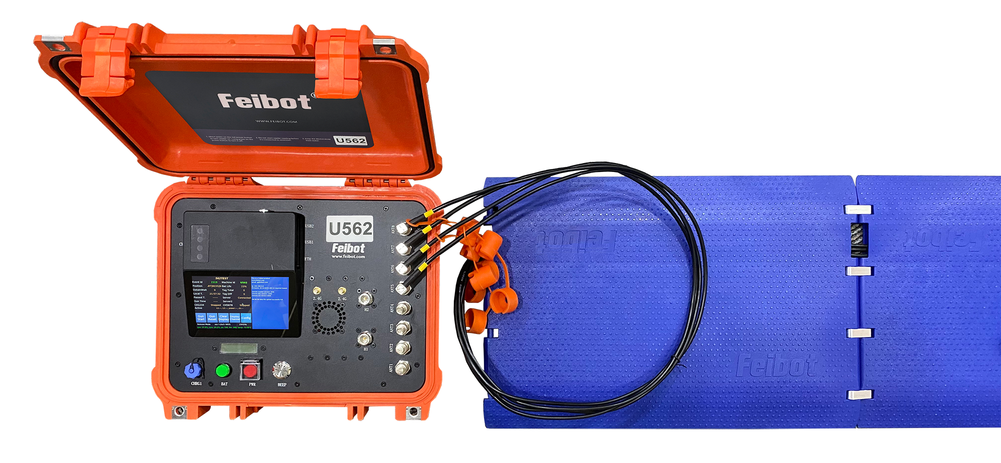
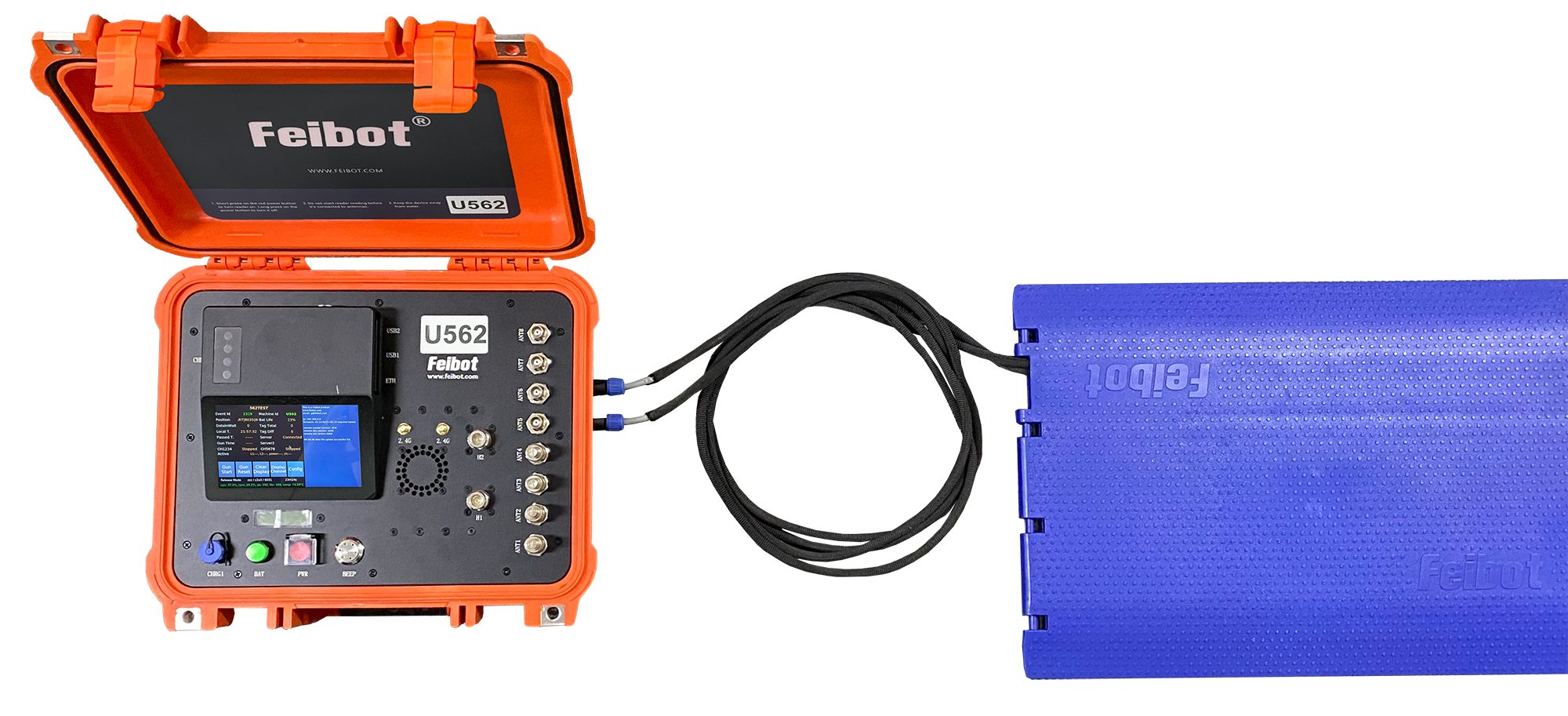
When using the passive system feature, the FMA2 mat antenna or the FMA2/FMA3 Pro mat needs to be connected. During use, simply spread it out flat.
(1) FMA2 Mat Antenna Layout
When connecting, ensure that the labels on the cables and the BNC connectors on the reader box correspond one-to-one.
(2) FMA2/FMA3 Pro Mat Layout
II. User Guide
1. Main Interface

- Event Id: After downloading the event config file from the Run8 Cloud backend, the screen will display the event Id of the event to which the current device belongs.
- Position: The position information of the device configured in the network backend.
- DatalnWait: The total number of data the reader box has read but not yet uploaded to the backend.
- Local T.: The current device's time in hours, minutes, and seconds. Make sure to calibrate the time before the event.
- Passed T.: The elapsed time of the current event.
- Gun Time: The time when the starting gun is fired in this event.
- The current reading state of the passive module.
- The current reading state of the active module, including LF loop cables, power, and channels.
- Event Name: Displays the event name of the event to which the current device belongs.
- Machine Id: The machine Id of this device.
- Bat Life: The current bat life of the device.
- Tag Total: The total number of tag data read by the current device.
- Tag Diff: The number of different tags detected by the current device.
- Server1/2: Displays the current device's network state. There are three possible states: "Not Connected to Network," "Connected to Network but Not to Backend," and "Connected to Backend."
- Gun Start: After clicking, it starts recording the firing time of the starting gun for this event.
- Gun Reset: After clicking, the firing time of the starting gun is reset to zero.
- Clear Display: After clicking, clears all content displayed on the right side.
- Display Channel: After clicking, you can choose to switch between active/passive modes.
- Config: After clicking, opens the config page.
- Displays the current mode of the device, with two options: "Normal Mode" and "Test Mode."
- Displays the current software/firmware version of the device.
- Displays the uptime of the device.
- Displays the CPU and RAM usage, as well as the number of processes and threads currently running on the operating system.
2. Config Interface
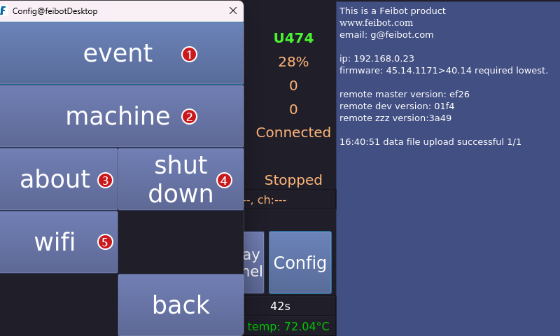
- Click to enter the "event" interface.
- Click to enter the "machine" interface.
- Click to enter the "about" interface.
- After clicking, you can choose to "Shut down" the device or "Reboot" the device.
- Click to enter the "WiFi" interface.
3. Event Interface
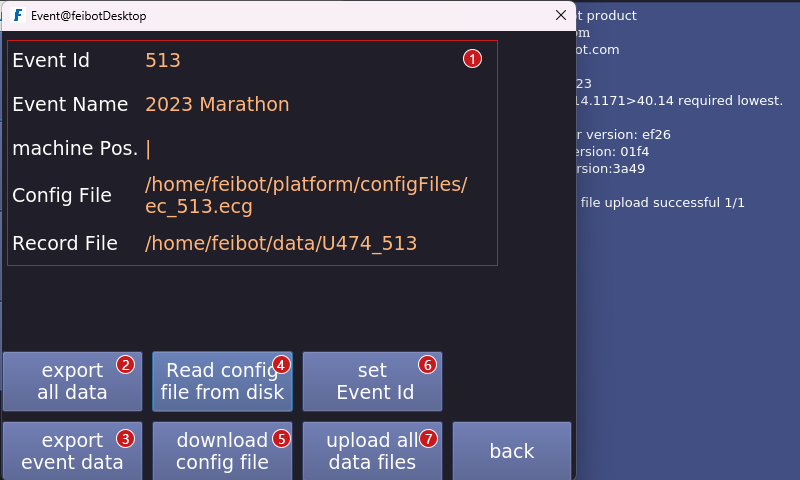
- Display information about the current event and the storage position of the event config file and data file in the backend.
- Export all the data of the events timed by this device.
- Export the data of the current event.
- Read the config file of the current event from the USB drive.
- Download the event config file (this button needs to be clicked before the event to download the event config file).
- Set the event Id.
- Upload all data files.
4. Machine Config Interface
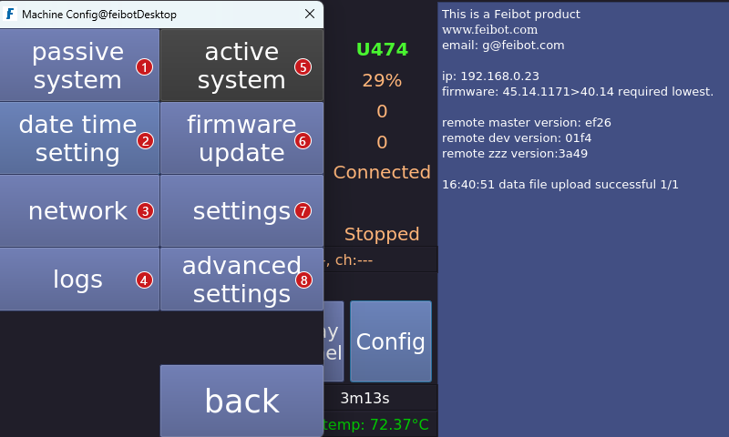
- Click to enter the "passive system" interface.
- Click to enter the "date time settings" interface.
- Click to enter the "network" interface.
- Click to enter the "logs" interface.
- Click to enter the "active system" interface.
- Click to enter the "firmware update" interface.
- Click to enter the "settings" interface.
- Click to enter the "advanced settings" interface.
5. Switch Interface
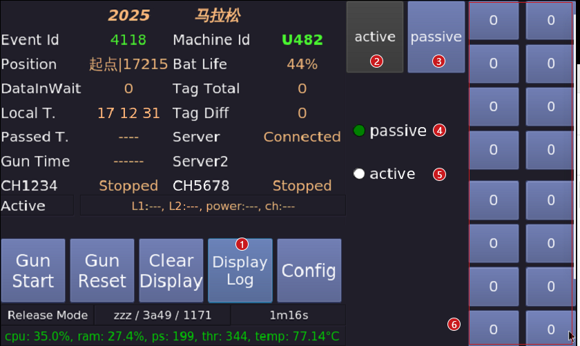
- Click to close and switch active/passive interface, return to text interface.
- Click to enter active settings interface.
- Click to enter passive settings interface.
- Passive switching button.
- Active switching button.
- Left side shows the channel status of the two external readers with 8 channels. Right side sh-ows the channel status of the two embedded readers with 8 channels.
6. Active System Interface
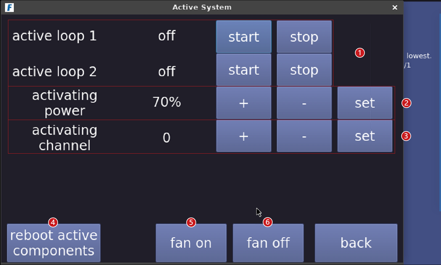
- Turn on/off low-frequency trigger 1/2.
- Increase/decrease trigger power, with a maximum of 100% and a minimum of 0%. The higher the trigger power, the better the reading effect.
- Select trigger channel, with channels 0 to 5 available. The communication distance decreases from channel 0 to channel 5.
- Reboot active components: Reboot the high-frequency module of the A400 active reader box.
- Turn on the fan.
- Turn off the fan.
7. Passive System Interface
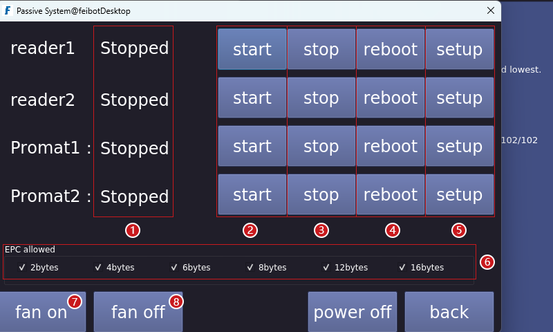
- Display the current status of the reader.
- Click the "start" button for the corresponding reader, and the reader will start reading data.
- Click the "stop" button for the corresponding reader, and the reader will stop reading data.
- Click the "reboot" button for the corresponding reader to reboot the reader.
- Click the "setup" button for the corresponding reader to enter its settings interface.
- Select the allowed EPC byte length for the reader.
- Turn on the fan.
- Turn off the fan.
8. Reader Setting Interface
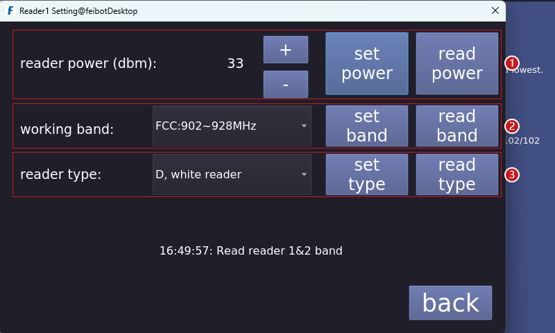
- Set reader power. The higher the power, the better the reading effect.
- Set working band.
- Set reader type.
9. Time and Date Setting Interface
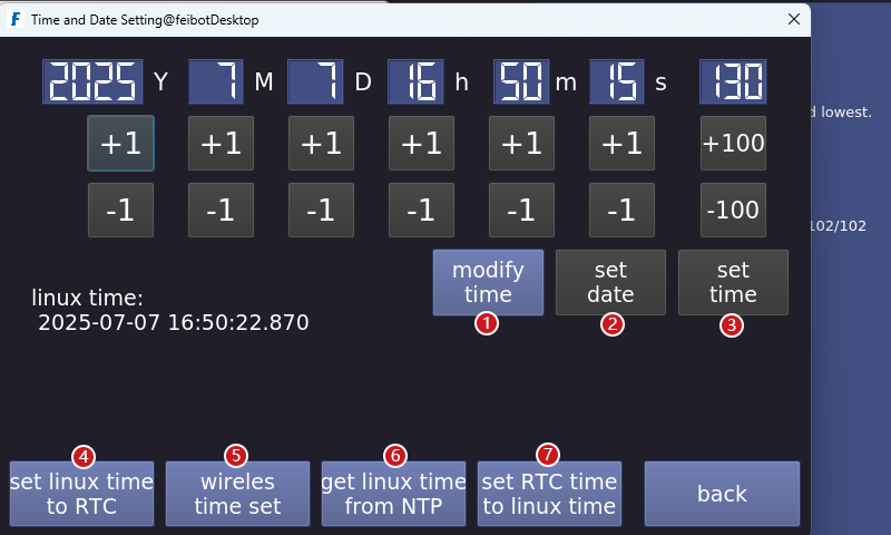
- Manually adjust the time by clicking the "+1" or "-1" button above to set the correct time.
- If the date is manually modified, you need to click the "set date" button.
- If the time is manually modified, you need to click the "set time" button.
- Set linux time to RTC.
- Wireless time set.
- Get linux time from NTP.
- Set RTC time to linux time.
10. Network Setting Interface
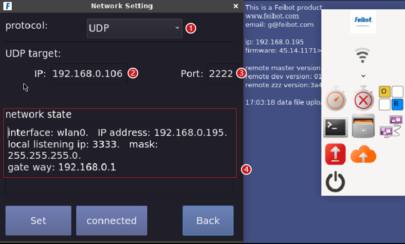
- Click the drop-down box next to the network protocol, and select either "UDP" or "TCP."
- You can set the local IP.
- You can set the port number.
- Display the current network state.
11. Log files Interface
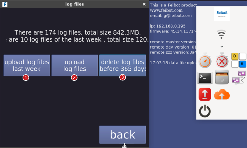
- Upload log files last week.
- Upload all log files.
- Delete the log files before 365 days.
12. Software Update Interface
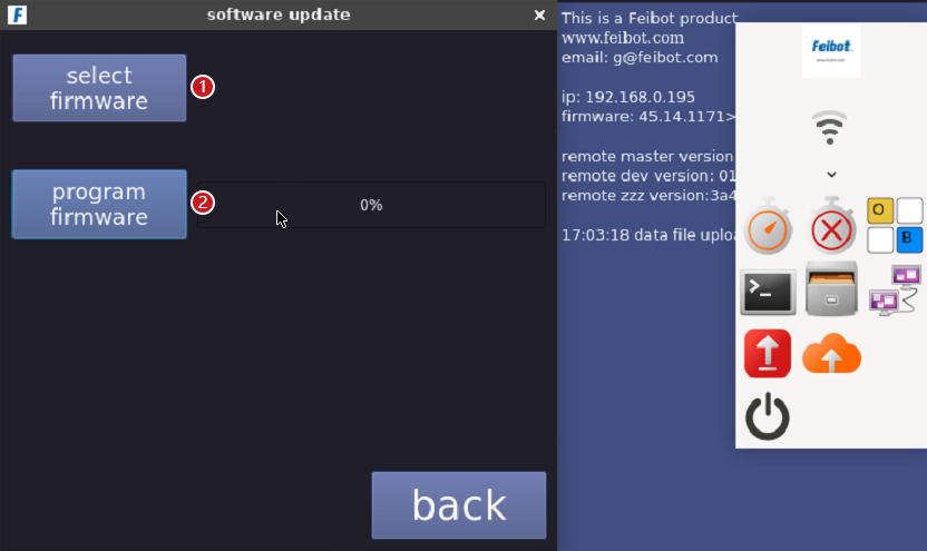
- Click the "select firmware" button. Select the firmware to update, then click the "open" button.
- Click the "program firmware" button to start programing the firmware, and wait for the process to complete before rebooting the reader box.
13. Settings Interface
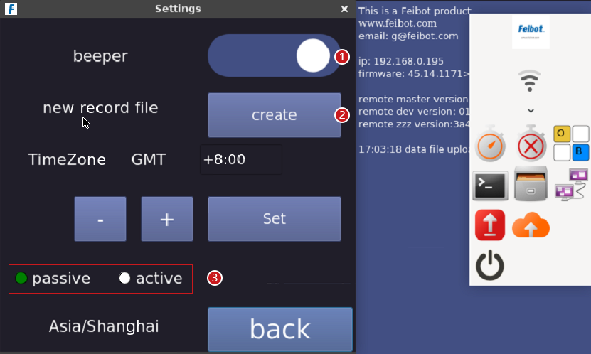
- Click the button to control the beepr switch.
- Create a new record file.
- Passive/Active system switch.
14. Advanced Setting Interface
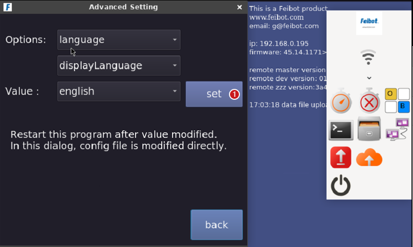
- In the language settings, enter "chinese" "enelish" or "traditionalchinese," After entering the language, click "set" and "set valve Ok!" will appear below, indicating that the setting is successful. You can then reboot the reader box, and the language will be changed.
15. About Interface
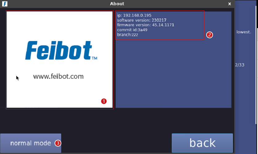
- About our company.
- About reader lP, software version, firmware version, branch version ID and branch.
- After clicking, you can choose between "Test Mode" and "Normal Mode." When upgrading the software, select "Test Mode" for the upgrade, and switch to "Normal Mode" once the version is stable.
16. Icon Feature
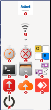
- Enter the application.
- WiFi connection.
- Start the software.
- Terminate the software.
- Turn on the keyboard.
- Open the terminal.
- Open the device's storage files.
- Advanced network settings.
- Upgrade to the latest stable version.
- Upgrade to the latest test version.
- Enable remote connection.
- Turn off the device.
