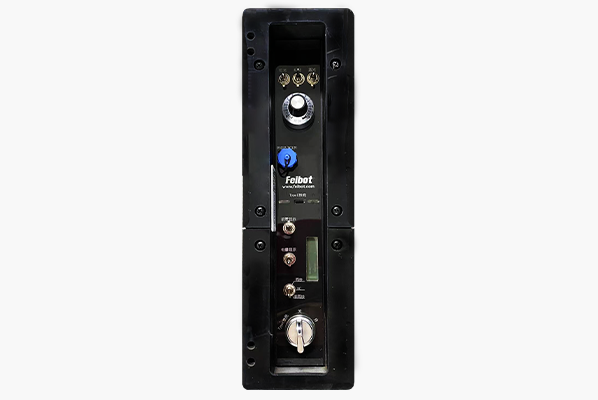
User Guide

FB2-LED Clock and FB2 Mechanical Clock are controlled by the same applet and Android APP. Multiple LED clocks within the range can be controlled simultaneously by connecting the data link through the Android APP, or two clocks can be used in combination.

Ⅰ. Mini Program

1. Log in with password to avoid misoperation by other people. Passwords can be obtained from the RUN8 Cloud backend. Passwords can be changed every 24 hours, or they can be modified in time through manual changes.
2. Turn on the clock, and then click connecting the clock through Bluetooth to connect the nearby clocks, it can be controlled in turn.
3. After connecting the clock bluetooth, the red area in the upper left corner shows that the bluetooth has been connected to the"xxx" clock. The clock plate is controlled through the software function buttons to display the required time information.
Notice:
1. Press the Start button and the clock plate starts to time.
2. Press the Pause button and the clock plate stops at the current state.
3. Press the Zero button and the clock plate will immediately return to zero, and it will be displayed as 0:00:00.
4. Press the Add One Second button, adding 1 second to the clock plate in the current state.
5. Press the Reduce One Second button, reducing 1 second to the clock plate in the current state.
6. Press the Equivalent Start Time button to set the time when the match is fired, and the clock starts from the set time.
7. Enter a number that conforms to the time logic inside the dial box, pressing the Set Dial button to display the time information what you set.

Ⅱ. APP

1. Open the APP and enter the main interface of the APP.
2. Click"Cloud Management" in the lower right corner to go to the next step.
3.Click"Login" in the upper left corner to enter your account password. example: 2020shtmls, password: 123456.
4. After entering your account and password, you can see all the clocks under the account.
5. Click the"Bluetooth" option in the lower left corner, click the clock button to connect to the Bluetooth, and go to the next step.
6. Connect the clock which you need to control. After connecting successfully, using the APP function buttons to control the clock.
Notice:
1. Press the Start button, the clock plate starts to time.
2. Press the Pause button, the clock plate stops at the current state.
3. Press the Zero button, the clock plate will immediately return to zero, and it will be displayed as 0:00:00.
4. Press the Add One Second button, clock plate will add 1 second in the current state.
5. Press the One Second button, clock plate will reduce 1 second in the current state.
6. Press the Equivalent Start Time button, setting the time of the match shooting, and the clock starts from the set time.
7. Enter a number that conforms to the time logic inside the dial box, and press the Set Dial button to display the time information what you set. Enter any of the specified commands"92221", "92222", and"92223", and then click the set dial, and then press the command button of the starter and the clock. The command gun after the frequency is used to control the clock clock with the frequency. A clock can be used to match the frequency with up to 3 starters. The clock can be controlled by the 3 starters with good frequency. Enter the specified command"93333" to delete all command guns that are over frequency with the clock.
8. When the clock is timing or pausing, pressing the Countdown button, and the clock starts to countdown, and stops after the countdown is"0:00:00".
9. Clock score display function: The clock is connected to the UHF chips card readers, reading the EPC code information of the UHF electronic tags, and accessing the Run8 Cloud backend through the mobile APP connected by Bluetooth. The clock can display the completion results corresponding to the UHF tags. You can also display the corresponding scores of this tag by manually entering the competition number.
10. Equivalent start time: Enter the Beijing time of the start time, click to start the positive timing from that time, and the clock displays the game duration from the start time.
11. Sleep clock: Make the clock enter low-power mode, and can only perform normal operation after wake-up.
12. Deep sleep: Turn off the clock network while entering low-power mode, and only normal operation can be performed after wake-up.
13. Wake up clock: Wake up the clock in sleep state.
14. Appointment wake-up: After the clock slept, you can make a reservation for a certain period of time and let the clock automatically wake up. It can be used to wake up the clock in deep sleep or normal sleep modes.
15. Clock restart: Restart the main clock program.
16. Refresh the dial: Push all digital chips of the clock once.
17. Test the dial: Test all digital displays(0-9) to check whether the digital chips are normal.
18. Countdown to the target time: Select a certain moment after the current moment, and the clock countdown to zero when it reaching that moment, or starting regular timing.
19. Display 12/ 24 hour time: Used to switch clock time display mode.
20. Timing settings: Used to time the mobile phone to give the clock at the moment, and is often used to unify the reference time of multiple clocks.

Ⅲ. Device

1. Side Panel Introduction

Notice
The control switches on the side control board all use rocker arm switches. Except for the synchronous rocker switches are three-speed switches, the other rocker arm switches are two-speed switches. The two-speed rocker switches have the rocker arm facing upwards and the rocker arm facing downwards as closes. The third-speed rocker switches have the rocker arm facing upwards, and the rocker arm is centered and the rocker arm facing downwards is open. The specific functions of each rocker switch will be described in detail below.
1. Three rocker switchesR, G, and B on the top of the side control panel control the clock color, and there are 6 colors to adjust: red, green, blue, yellow, purple and 0
cyan.
Rocker switch RRocker switch G Rocker switch BColor
updowndownred
downupdowngreen
downdownupblue
upupdownyellow
upupupyellow
downdowndownyellow
updownuppurple
downupupcyan
2. The brightness adjustment knob realizes the adjustment of the brightness of the clock, and the brightness adjustment is divided into 11 stops 0, 10%, 20%, 100%. The 0 gear is set to the minimum brightness, and the brightness of other gears increases as the value increases.
Notice
It is recommended to rotate the scale line of the brightness knob to the opposite percentage number to avoid brightness jump.
3. The score display terminal needs to be connected to the score sensing board to achieve the score displayed.
4. The front zero display rocker switch controls whether the front zero is displayed or not. The rocker arm up indicates the front zero displayed, and the rocker arm down indicates the front zero didn't display. In this state, the digital board only has the second and small dots. As the timing carrying, the minute and time positions will lit up one after another. The purpose of this design is to save power.
5. The power display rocker arm switch is used to control whether the power display module is working. The rocker arm displays the power upward, and the rocker arm closes the power display downward.
6. The synchronous rocker switch is used to control whether other clock signals are synchronized, and it needs to be used with another clock through a synchronization line. There are three states for synchronous rocker switches: the rocker arm is facing up and the synchronization function needs to be activated, and the driving signals of other clocks need to be connected to the driving signals of other clocks to work; the center of the rocker arm is turned off. The clock in this state does not work; the clock in the clock down is working with its own driving signals.
Notice
The concept of synchronization here is to make the time displayed by two clocks completely synchronize without deviation. The application scenario is when two clocks are required to be displayed at the same time. The original intention of designing the synchronization function is to make the times of the two clocks fully synchronized. After the synchronization function is turned on, the signal of the other clock is directly supplied to this clock. This can absolutely ensure that the time display of the two clocks will not cause offsets with the increase of time to achieve full synchronization. Therefore, if the synchronization function is not required, be sure to turn the synchronization rocker arm switch rocker downwards so that the clock is in normal working state.
7. There are three states for switch locks: on, off, charging. Here, we focus on the charging status. When the key twists to the switch lock charging position, you can use the typeC charger to charge the clock.
Notice
When the clock working normally, you cannot charge the clock by using typeC charger. Be sure that the key is twisted to the switch lock charging position and then use the typeC charger to charge. This clock only supports typeC chargers with PD fast charging, and the power is recommended to be greater than 60W for optimal charging effect. It is recommended to use gallium nitride typeC charger and typeC data cable that supporting PD fast charging above 60W. This charging function is a backup to prevent the main charger from failing or losing, and is used for emergency use!

2. Top Interface Introduction

The top interface of the clock is from left to right: wireless serial port(data link), main charging port, and synchronization line interface.
1. The wireless serial port needs used with 170M glue rod antenna, which can receive control signals from our gun type generators and data links related products to realize wireless controlling functions such as starting or stopping timing.
2. The main charging port is used with the charger provided by our company.
Notice
The main charging port can charge the clock regardless of whether the clock working or not, which is different from typeC charging. Be careful not to charge the clock with main charger and typeC charger at the same time, avoiding damaging the battery. If clock need high brightness or long-term operation, you can use the main charger to connect to an external power supply while charging.
3. Synchronous line interface: When the synchronization function of clock 1 is turned on, the driving signal is obtained from clock 2 by using a synchronization line connection.
Notice
The implementation of the synchronization function requires two clocks used together through the synchronization line. If clock 1 uses the synchronization function, the synchronous rocker switch rocker arm needs upward: clock 2 synchronous rocker switch rocker arm needs downward. After connecting through the synchronization line, clock 1 uses the driving signal of clock 2 to ensure that the two clocks are fully synchronized.
2025-06-27